Ale Lagrangian Formulation With Continuous Test Spaces
Introduction
Numerical simulation of the tire production process involves the irreversible change in material properties due to its transformation from the green state to the cured state. This process requires molding the green rubber under pressure loading and the application of high temperature to induce the vulcanization reaction. Molding typically leads to large geometrical changes of the tire profile to achieve the desired final shape. The description of rubber in its green and cured phases as well as the transition between the two phases as a single material model has been recently proposed in [1, 10]. In these works, material models are formulated using finite strain theory and utilizing the multiplicative split of the deformation gradient, which allows the use of advanced inelastic rubber models. However, the potential of these models in finite element tire manufacturing simulations cannot be fully realized due to the large distortions encountered during molding of rubber using standard Lagrangian finite element codes. It is, thus, beneficial to enhance the standard Lagrangian formulation with a remeshing technique. In this context, one can use general adaptive remeshing methods, which change the data structure and require remapping the whole description and its solutions. A special kind of adaptive remeshing can alternatively be achieved by the Arbitrary Lagrangian–Eulerian (ALE) formulation, which does not change the number of finite elements or their connectivity, but only the location of the nodes.
The conventional approach to solve finite element equations in solid mechanics is to attach the material points to the spatial mesh. This pure Lagrangian description remarkably simplifies the solution algorithms as well as enables a direct tracking of material boundaries. Moreover, history variables required for inelastic materials can be assigned to a unique reference point, which does not change throughout the incremental solution. An obvious limitation of this method is, however, that severe mesh distortion and entanglement can occur in case of large strains and localized inelastic deformations. In contrast, material in the Eulerian description is free to move with respect to a fixed spatial mesh. This means that no distortion in the mesh can occur, but tracking the boundaries and the material history becomes complex. The weaknesses of the two aforementioned methods in large deformation analysis motivated the development of the ALE description, which seeks to combine the best of both approaches. In this formulation, the finite element mesh is not attached to the material or kept fixed in space. Rather, it partially follows the material while at the same time it is continuously moved relative to the material in order to reduce element distortions. Thus, the ALE description has the potential for solving a variety of complex problems dealing with large deformation, especially in forming and molding simulations [14, 15].
Though originally developed for fluid mechanics [16], ALE formulations have quickly found their way into solid mechanics [9, 17, 29]. However, early developments have avoided the use of material laws based on hyperelasticity and the multiplicative split of deformation gradient, opting for rate models and hypoelastic relations. The reason for this restriction is the absence of the material configuration in these formulations, where they are usually described by velocity based variables. Thus, it becomes difficult to obtain a total deformation gradient, which is crucial for the analysis of hyperelastic materials such as rubber. Two approaches have been proposed to solve this limitation. The first, introduced in [26], is similar to the conventional ALE formulations, where it introduces an incremental deformation gradient and requires the transportation of the elastic strains in addition to the plastic history variables. The second method, proposed in [30] for hyperelasticity and developed in [2, 21] for multiplicative plasticity, introduces the material configuration as a part of the formulation. This fact enables the evaluation of the total deformation gradient, without the need of remapping any of the elastic variables. Moreover, it allows the use of a material particle tracking scheme for the inelastic history variables.
An essential part in the ALE approach is the mesh improvement scheme. To this end, several remeshing techniques can be found such as, arbitrary user-defined motion, volume-weighted smoothing, Laplacian smoothing and equipotential smoothing [5]. More advanced approaches such as adaptive rezoning for fluid-structure interaction [22] and optimization-based mesh motion [4] have also been proposed. In this work, the smoothing follows the approach in [2, 30] by solving a boundary value problem based on a fictitious elastic model to optimize the material and the spatial meshes at the same time.
ALE equations can be solved as a monolithic fully coupled problem as proposed by [3, 30] for elasticity and [8, 12] for inelasticity. However, the staggered stepwise solution is more common, because it minimizes the computational time for ALE calculations and enables the use of the already available Lagrangian formulation as a substep of the new approach.
In order to account for the relative velocity between the material particles and the spatial mesh, a proper history remapping algorithm is also required. The most widely used approaches in this context are explicit methods [25], such as the Lax–Wendroff scheme, which requires the computation of a smooth gradient of the advected variables. Alternatively, Godunov's scheme avoids the need for averaging to obtain smooth spatial gradients. However, in both cases, the advection needs to be performed for each component of the history variable, which make them expensive for material models with a high number of history variables. Moreover, these advection methods can lead to inadmissible values of the history such as a negative equivalent plastic strain. The ALE approach used in this work, by the incorporation of the material mesh in the calculations, offers an alternative way for the remapping of history through tracking of the material particles. This means that the location of a particle before and after the smoothing step is exactly known, and can be used to reassign the history variables regardless their number. Thus, this method is well-suited for the large number of history variables as involved in rubber curing models.
In this paper, an ALE finite element formulation for the analysis of the general case of thermomechanical finite strain models will be presented. It starts with the description of the ALE kinematics and the staggered solution approach. Next, a mesh smoothing approach is introduced and the history remapping algorithm is explained. In Sect. 3, the thermomechanically coupled rubber vulcanization model is described. Finally, numerical examples to demonstrate the capabilities of the developed approach as well as rubber molding and curing simulations are carried out.
Arbitrary Lagrangian–Eulerian formulation
ALE kinematics
The deformation mapping in the Lagrangian description is constructed by defining the motion with respect to the material configuration, which is fixed at the initial configuration. The material and the initial configuration are in this case equivalent and are used as the reference configuration. The ALE description, on the other hand, introduces a reference configuration, which is independent of both the material and spatial configuration. If the reference configuration is fixed at the initial configuration, see Fig. 1, a special formulation is achieved, where the position of the material and the spatial coordinates for a reference point \({\mathbf {m}}\) at a time t can be defined in terms of the material mapping \({\mathcal {X}}\) and the spatial mapping \({{\psi }}\) as follows
$$\begin{aligned} {\mathbf {X}}_{t}={\mathcal {X}}\left( {\mathbf {m}},t\right) \;\text {,}\qquad {\mathbf {x}}_{t}=\psi \left( {\mathbf {m}},t\right) . \end{aligned}$$
(1)
The physical deformation can then be calculated by the composite mapping \(\varphi \) as
$$\begin{aligned} \varvec{\varphi }=\psi \circ {\mathcal {X}}^{-1}. \end{aligned}$$
(2)
The deformation gradients corresponding to the above mappings, then, can be calculated as follows
$$\begin{aligned}&\mathbf {F_{\psi }}=\nabla _{{\mathbf {m}}}\psi =\frac{\partial {\mathbf {x}}}{\partial {\mathbf {m}}}, \end{aligned}$$
(3)
$$\begin{aligned}&{\mathbf {F}}_{{\mathcal {X}}}=\nabla _{{\mathbf {m}}}{\mathcal {X}}=\frac{\partial {\mathbf {X}}}{\partial {\mathbf {m}}}, \end{aligned}$$
(4)
where \(\nabla _{{\mathbf {m}}}=\text {Grad}_{{\mathbf {m}}}\) is the gradient operator with respect to the reference configuration. The physical deformation gradient is then calculated from the previous expressions as
$$\begin{aligned} {\mathbf {F}}=\mathbf {F}_{\psi }{\mathbf {F}}_{{\mathcal {X}}}^{-1}. \end{aligned}$$
(5)
The material and the spatial displacements can also be defined as
$$\begin{aligned} {\mathbf {u}}_{{\mathcal {X}}}={\mathcal {X}}\left( {\mathbf {m}},t\right) -{\mathbf {m}}\;\text {,}\qquad {\mathbf {u}}_{\psi }=\psi \left( {\mathbf {m}},t\right) -{\mathbf {m}}. \end{aligned}$$
(6)
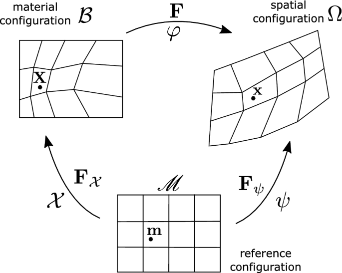
ALE kinematics with the initial configuration as the reference configuration
Furthermore, the boundary conditions on the material configuration \({\mathcal {B}}\) should be imposed in such a way (to preserve the material character), that the material motion should not cause any in- or outflow of material through the boundary, which implies the condition
$$\begin{aligned} {\mathbf {V}}_{{\mathcal {X}}}\cdot {\mathbf {N}}=0\quad \text {on}\quad \partial {\mathcal {B}}=\partial \mathcal {{\mathscr {M}}}, \end{aligned}$$
(7)
where \({\mathbf {V}}_{{\mathcal {X}}}=\partial {\mathbf {X}}/\partial t\) is the material velocity and \({\mathbf {N}}\) is the unit vector normal to the boundaries \(\partial {\mathcal {B}}=\partial \mathcal {{\mathscr {M}}}\). This condition simply enforces zero material motion normal to the boundary, while the tangential motion is still permitted. It is worth noting that for a straight segment of the boundary, the normal vector \({\mathbf {N}}\) is same for the whole segment, and, thus, \({\mathbf {N}}\) corresponding to a material point moving along this segment will not change over time, which allows the integration of the boundary condition over time as \(\int _{t}\left( {\mathbf {V}}_{{\mathcal {X}}}\cdot {\mathbf {N}}\right) dt=\int _{t}{\mathbf {V}}_{{\mathcal {X}}}dt\cdot {\mathbf {N}}={\mathbf {u}}_{{\mathcal {X}}}\cdot {\mathbf {N}}.\) This allows the above boundary condition to be simplified for straight segments of the boundary as follows
$$\begin{aligned} {\mathbf {u}}_{{\mathcal {X}}}\cdot {\mathbf {N}}=0\quad \text {on}\quad \partial \mathcal {{\mathscr {M}}}, \end{aligned}$$
(8)
which may not always be possible to apply if the external boundary of the initial problem is complex. This can be circumvented by defining the ALE domain in uniform segments of the geometry, because, in most cases, high distortion occurs in specific locations.
Staggered ALE algorithm
The material degrees of freedom introduced in the previous section can be solved in a fully coupled simultaneous manner along with the spatial degrees of freedom. Such a solution, however, will be computationally inefficient. The alternative, more common strategy to solve ALE formulations is the use of staggered schemes. The global solution in this case can be outlined in the following three steps. First, a smoothing step is performed to calculate \({\mathbf {u}}_{{\mathcal {X}}}\) holding \({\mathbf {u}}_{\psi }\) fixed in order to minimize a certain mesh distortion measure. In the second step, the history is remapped for the modified mesh. Finally, a Lagrangian step to calculate \({\mathbf {u}}_{\psi }\) while holding \({\mathbf {u}}_{{\mathcal {X}}}\) fixed is performed to solve the governing balance equations of the problem at hand. In this way, the ALE calculation reduces to solving the same size of the problem as the Lagrangian case, but with the addition of several iterations for the smoothing phase. As suggested in [2], the Lagrangian step is solved at the end of the time step and not at the beginning in order to ensure that the governing equations are satisfied. Moreover, it is in general not required to perform smoothing at every time step, rather it can be performed after several pure Lagrangian steps. Each phase will be described in detail in the following sections. An example of how the staggered ALE algorithm can be executed with ns as the total number of time increments and na the number of ALE smoothing steps is outlined in Algorithm 1.

Mesh smoothing
The main aim of ALE formulations is to limit the distortion of the spatial mesh. The method proposed in [2] achieves this goal by choosing a material displacement field \(\tilde{{\mathbf {u}}}_{\tilde{{\mathcal {X}}}}\), which minimizes both the spatial mesh distortion as well as the material mesh distortion based on the following minimization problem
$$\begin{aligned} \tilde{{\mathbf {u}}}_{\tilde{{\mathcal {X}}}}=\underset{\tilde{{\mathbf {u}}}_{\tilde{{\mathcal {X}}}}}{\text {arg min}}\left[ \varPi _{sm}\left( \tilde{{\mathbf {u}}}_{\tilde{{\mathcal {X}}}}\right) \right] , \end{aligned}$$
(9)
for a fixed physical deformation \({\mathbf {F}}_{n}\), where the functional \(\varPi _{sm}\) defines the distortion of the meshes by the scalar potential function \(W_{sm}\) as
$$\begin{aligned} \varPi _{sm}\left( \tilde{{\mathbf {u}}}_{\tilde{{\mathcal {X}}}}\right)&{:=}\int _{{\mathscr {M}}}W_{sm}\left( \mathbf {F}_{{\tilde{\psi }}}, \mathbf {F}_{\tilde{{\mathcal {X}}}}\right) d{\mathscr {M}}\nonumber \\&=\int _{{\mathscr {M}}}W_{sm}\left( \bar{{\mathbf {F}}}_{n}\mathbf {F}_{\tilde{{\mathcal {X}}}}, \mathbf {F}_{\tilde{{\mathcal {X}}}}\right) d{\mathscr {M}}, \end{aligned}$$
(10)
where definitions for \(W_{sm}\) will be discussed later in the section and the function
$$\begin{aligned} \bar{{\mathbf {F}}}_{n}=f({\mathbf {F}}_{n})\, \end{aligned}$$
(11)
is used to allow the consideration of certain components of the deformation for smoothing. If it is simply taken as \(\bar{{\mathbf {F}}}_{n}={\mathbf {F}}_{n}\), then, the smoothing is applied to the three displacement components. The variation of the functional in Eq. (10) with respect to the material deformations provides the boundary value problem to solve the minimization problem as follows
$$\begin{aligned} \delta \varPi _{sm}&=G_{sm}\nonumber \\&= \int _{{\mathscr {M}}}\left[ {\mathbf {F}}_{\tilde{{\mathcal {X}}}}{\mathbf {S}}_{{\tilde{\psi }}}+{\mathbf {F}}_{\tilde{{\mathcal {X}}}}{\mathbf {S}}_{\tilde{{\mathcal {X}}}}\right] :\text {Grad}_{{\mathbf {m}}}\left( \delta {\mathcal {X}}\right) d{\mathscr {M}}, \end{aligned}$$
(12)
where \({\mathbf {S}}_{\tilde{{\mathcal {X}}}}\) and \({\mathbf {S}}_{{\tilde{\psi }}}\) are second Piola Kirchhoff pseudo-stresses given as
$$\begin{aligned} {\mathbf {S}}_{\tilde{{\mathcal {X}}}}=\left. 2\frac{\partial W_{sm}}{\partial {\mathbf {C}}_{\tilde{{\mathcal {X}}}}}\right| _{\mathbf {F}_{{\tilde{\psi }}}}\quad \text {and}\quad {\mathbf {S}}_{{\tilde{\psi }}}=\left. 2\frac{\partial W_{sm}}{\partial {\mathbf {C}}_{{\tilde{\psi }}}}\right| _{\mathbf {F}_{\tilde{{\mathcal {X}}}}}. \end{aligned}$$
(13)
The fixed physical deformation gradient is calculated as \({\mathbf {F}}_{n}={\mathbf {F}}_{\psi n}{\mathbf {F}}_{{\mathcal {X}}n}^{-1},\) using deformation gradients \({\mathbf {F}}_{{\mathcal {X}}n}\) and \({\mathbf {F}}_{\psi n}\) of the previous time step, considering that \(n+1\) is the current time step. This leads to the spatial deformation gradient in terms of the material mapping as follows
$$\begin{aligned} \mathbf {F}_{{\tilde{\psi }}}=\bar{{\mathbf {F}}}_{n}\mathbf {F}_{\tilde{{\mathcal {X}}}}. \end{aligned}$$
(14)
Distortion measures for FE meshes have been studied in the context of automatic mesh generation [13, 20, 23]. In [23], a distortion metric for isoparametric elements has been proposed drawing the analogy between element distortion and strain, where the deviation of an element from an ideal shape is considered similar to bodies experiencing strains. Thus, any invariant scalar energy function may be used to measure mesh distortion, where the only condition is that it should be purely deviatoric, since volumetric changes do not indicate distortion. The following function is used
$$\begin{aligned} W_{sm}=\frac{1}{2}\mu _{\psi }\left( {\bar{I}}_{C}\left( \bar{{\mathbf {F}}}_{n}\mathbf {F}_{\tilde{{\mathcal {X}}}}\right) -3\right) +\frac{1}{2}\mu _{{\mathcal {X}}}\left( {\bar{I}}_{C}\left( {\mathbf {F}}_{\tilde{{\mathcal {X}}}}\right) -3\right) ,\nonumber \\ \end{aligned}$$
(15)
where \({\bar{I}}_{C}\) is the first invariant of the isochoric part of \({\mathbf {C}}\), defined as
$$\begin{aligned} {\bar{I}}_{C}\left( {\mathbf {F}}\right) =J^{-\frac{2}{3}}\text {tr}({\mathbf {C}}),\text {with}\quad J=\det \left( {\mathbf {F}}\right) , \end{aligned}$$
(16)
and \({\mathbf {C}}={\mathbf {F}}^{T}{\mathbf {F}}\) is the right Cauchy–Green deformation tensor. As can be seen, the utilized smoothing potential is similar to energy functions used in hyperelasticity. Furthermore, the parameters \(\mu _{{\mathcal {X}}}\) and \(\mu _{\psi }\) control the smoothing process through the ratio \(\mu _{{\mathcal {X}}}/\mu _{\psi }\), while their absolute value is not relevant. It is worth noting that reducing the distortion in the two meshes are competing objectives, when solving Eq. (12), where \(\mu _{{\mathcal {X}}}/\mu _{\psi }=\infty \) retrieves the Lagrangian formulation while \(\mu _{{\mathcal {X}}}/\mu _{\psi }=0\) means maximum smoothing of the spatial mesh on the expense of the material mesh. A value of \(\mu _{{\mathcal {X}}}/\mu _{\psi }=0\) is, however, not the optimum choice, because it causes excessive distortion and entanglement in the material mesh, what may lead to failure in history remapping algorithms.
The solution of Eq. (12) follows the same procedures used in the linearization of finite strain equations in the reference configuration, see "Appendix A". The potential function definition in Eq. (15) leads to the following pseudo stresses
$$\begin{aligned}&{\mathbf {S}}_{\tilde{{\mathcal {X}}}}=\mu _{{\mathcal {X}}}J_{\tilde{{\mathcal {X}}}}^{-\frac{2}{3}}\left( {\mathbf {1}}-\frac{1}{3}\text {tr}({\mathbf {C}}_{\tilde{{\mathcal {X}}}}){\mathbf {C}}_{\tilde{{\mathcal {X}}}}^{-1}\right) , \end{aligned}$$
(17)
$$\begin{aligned}&{\mathbf {S}}_{{\tilde{\psi }}}=\mu _{{\psi }}J_{{\tilde{\psi }}}^{-\frac{2}{3}}\left( {\mathbf {1}}-\frac{1}{3}\text {tr}({\mathbf {C}}_{{\tilde{\psi }}}){\mathbf {C}}_{{\tilde{\psi }}}^{-1}\right) . \end{aligned}$$
(18)
Pseudo tangents \({\mathbb {C}}_{\tilde{{\mathcal {X}}}}\) and \({\mathbb {C}}_{{\tilde{\psi }}}\) can then be obtained in a standard way as
$$\begin{aligned} {\mathbb {C}}&=2\frac{\partial {\mathbf {S}}}{\partial {\mathbf {C}}}=-\frac{2}{3}\mu J^{-\frac{2}{3}}\left[ {\mathbf {C}}^{-1}\otimes {\mathbf {1}}+{\mathbf {1}}\otimes {\mathbf {C}}^{-1}\right. \nonumber \\&\qquad -\, \left. \frac{1}{3}\text {tr}({\mathbf {C}}){\mathbf {C}}^{-1}\otimes {\mathbf {C}}^{-1}+\text {tr}({\mathbf {C}})\frac{\partial {\mathbf {C}}^{-1}}{\partial {\mathbf {C}}}\right] , \end{aligned}$$
(19)
where the derivative of the inverse of the symmetric tensor \({\mathbf {C}}\) reads
$$\begin{aligned} \frac{\partial {\mathbf {C}}_{ij}^{-1}}{\partial {\mathbf {C}}_{kl}}=-\frac{1}{2}\left( {\mathbf {C}}_{ik}^{-1}{\mathbf {C}}_{jl}^{-1}+{\mathbf {C}}_{il}^{-1}{\mathbf {C}}_{jk}^{-1}\right) . \end{aligned}$$
(20)
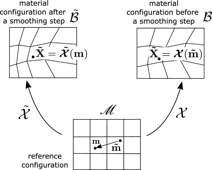
History remapping by material particle tracking
History remapping
The ALE approach discussed in the previous sections already includes the material configuration. This means that the displacement field \({\mathbf {u}}_{{\mathcal {X}}}\) represents the motion of the material particle \({\mathbf {X}}\) with respect to the fixed reference mesh coordinate \({\mathbf {m}}\). Thus, and as shown in Fig. 2, it is possible to backtrack location \(\tilde{{\mathbf {m}}}\left( {\mathbf {m}}\right) \) after a smoothing step by solving the following equation
$$\begin{aligned} \tilde{\varvec{{\mathcal {X}}}}\left( {\mathbf {m}}\right) =\varvec{{\mathcal {X}}}\left( \tilde{{\mathbf {m}}}\right) , \end{aligned}$$
(21)
which can be rewritten in terms of the reference coordinates and material displacements as
$$\begin{aligned} {\mathbf {m}}+\tilde{{\mathbf {u}}}_{\mathcal {{\tilde{X}}}}\left( {\mathbf {m}}\right) =\tilde{{\mathbf {m}}}+{\mathbf {u}}_{{\mathcal {X}}}\left( \tilde{{\mathbf {m}}}\right) . \end{aligned}$$
(22)
This equation, if written in the following residual form,
$$\begin{aligned} {\mathbf {r}}\left( \tilde{{\mathbf {m}}}\right) =\left[ \tilde{{\mathbf {m}}}+{\mathbf {u}}_{{\mathcal {X}}}\left( \tilde{{\mathbf {m}}}\right) \right] -\left[ {\mathbf {m}}+\tilde{{\mathbf {u}}}_{\mathcal {{\tilde{X}}}}\left( {\mathbf {m}}\right) \right] \end{aligned}$$
(23)
can be solved by the Newton Raphson iteration as follows
$$\begin{aligned} \tilde{{\mathbf {m}}}^{k+1}=\tilde{{\mathbf {m}}}^{k}-\left[ \frac{\partial {\mathbf {r}}}{\partial \tilde{{\mathbf {m}}}^{k}}\right] ^{-1}\cdot {\mathbf {r}}\left( \tilde{{\mathbf {m}}}^{k}\right) , \end{aligned}$$
(24)
which requires evaluating the derivative at every iteration as
$$\begin{aligned} \frac{\partial {\mathbf {r}}}{\partial \tilde{{\mathbf {m}}}}={\mathbf {1}}+\frac{\partial {\mathbf {u}}_{{\mathcal {X}}}\left( \tilde{{\mathbf {m}}}\right) }{\partial \tilde{{\mathbf {m}}}}={\mathbf {F}}_{{\mathcal {X}}}\left( \tilde{{\mathbf {m}}}\right) , \end{aligned}$$
(25)
where \({\mathbf {F}}_{{\mathcal {X}}}\left( \tilde{{\mathbf {m}}}\right) \) is the material deformation gradient before the last smoothing step, and not \({\mathbf {F}}_{\mathcal {\mathcal {{\tilde{X}}}}}\left( \tilde{{\mathbf {m}}}\right) \). The above particle tracking equation may require looking for \(\tilde{{\mathbf {m}}}\) and its corresponding displacement \({\mathbf {u}}_{{\mathcal {X}}}\left( \tilde{{\mathbf {m}}}\right) \) outside of the element, which needs an element search algorithm to determine the location of the iterative values \(\tilde{{\mathbf {m}}}^{k}\). Such an algorithm entails looping over all elements and checking if the point \(\tilde{{\mathbf {m}}}^{k}\) is inside the element. An algorithm for hexahedral elements based on the normal to element faces is shown in Fig. 3. Moreover, it is more efficient to check closer elements first, rather than to loop over the whole list of elements with no specific order. In most cases, the motion of the material is not very far from the original element.
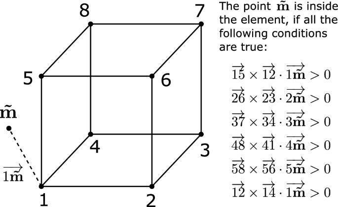
Algorithm to determine if a node lies inside or outside a given hexahedral element
After the element is located, it is then necessary to find the natural coordinates \({\tilde{\xi }}\) of the point \(\tilde{{\mathbf {m}}}\), using an inverse isoparametric mapping [31] solved again by the Newton method as follows
$$\begin{aligned} {\tilde{\xi }}^{i+1}= & {} {\tilde{\xi }}^{i}+{\mathbf {J}}_{\xi }^{-1}\left[ \tilde{{\mathbf {m}}}-\hat{{\mathbf {m}}}\left( {\tilde{\xi }}^{i}\right) \right] =0, \end{aligned}$$
(26)
$$\begin{aligned} {\mathbf {J}}_{\xi }= & {} {\sum \limits _{A}^{n_{node}}}\frac{\partial N_{A}}{\partial \xi }\left( {\tilde{\xi }}^{i}\right) {\mathbf {m}}^{A}. \end{aligned}$$
(27)
It is, however, unlikely that the determined coordinates \({\tilde{\xi }}\) will coincide with any integration point. Thus, one has to approximate where to assign the projected values. One possibility is to interpolate for the history variables at the element level. Alternatively, it is possible to use a simple discontinuous approximation, where every point \({\tilde{\xi }}\) is assigned to one quadrature point by dividing each element into domains where the history is considered constant. A hexahedral element with eight integration points can be divided into eight domains, where the quadrature point \(\xi _{1}\), for example, corresponds to the domain \(\left[ -1,0\right] \),\(\left[ -1,0\right] \),\(\left[ -1,0\right] \) in terms of the natural coordinates. If \({\tilde{\xi }}\) is then located in domain 1, the history is assigned to the quadrature point \(\xi _{1}\). This piecewise transfer ensures with no extra constraints the physical nature of the history variables. Finally, the projection follows by reassigning the history in the computer memory
$$\begin{aligned} \phi _{\text {projected}}\left( {\mathbf {m}}\right) =\phi _{\text {unprojected}}\left( \tilde{{\mathbf {m}}}\right) . \end{aligned}$$
(28)
A summary of the history projection process by particle tracking is outlined in Algorithm 2.

Lagrangian step
After the smoothing and the remapping steps, a Lagrangian step is carried out to solve the physical problem. In this step, the spatial map \(\psi \) is calculated, for a fixed material deformation gradient \({\mathbf {F}}_{\tilde{\mathcal {X}}}\), which is calculated by the smoothing step. In a thermomechanically coupled problem, it is then required to solve the balance of linear momentum
$$\begin{aligned} J\,\text {div}\left( \frac{\varvec{\tau }}{J}\right) +\rho _{0}{\mathbf {b}}=0 \end{aligned}$$
(29)
for the mechanical part along with the balance of energy
$$\begin{aligned} J\,\text {div}\left( {\mathbf {q}}\right) -r+c_{v}{\dot{\theta }}-w_{ext}-w_{int}=0 \end{aligned}$$
(30)
for the thermal part, where \(\varvec{\tau }\) is the Kirchhoff stress calculated from the deformation gradient \({\mathbf {F}}=\mathbf {F}_{\psi }{\mathbf {F}}_{\mathcal {\tilde{{\mathcal {X}}}}}^{-1}\), \(J=\det \left( {\mathbf {F}}\right) \) and \(\rho _{0}{\mathbf {b}}\) is the material volumetric body force, with \(\rho _{0}\) as the density in the material configuration. In the balance of energy equation, \({\mathbf {q}}\) is the heat flux in the spatial configuration, r represents a heat source, \(c_{v}\) is the heat capacity, \(\theta \) is the temperature, \(w_{ext}\) is the external power due to the rate of change of the displacement field and \(w_{int}\) is the internal power stemming from the evolution of internal variables. The heat flux is defined as
$$\begin{aligned} {\mathbf {q}}=-\frac{1}{J}k{{\nabla }}_{\varvec{\psi }}{\theta }, \end{aligned}$$
(31)
where the constant k is the heat conductivity coefficient. The weak forms of the above balance laws could be expressed with the help of the test functions \(\delta {\psi }\) and \(\delta {\theta }\) as
$$\begin{aligned} G_{M}&=\int _{{\mathscr {M}}}\varvec{\tau }:{{\nabla }}_{{\psi }}^{s}\left( \delta {\psi }\right) J_{\tilde{{\mathcal {X}}}}d{\mathscr {M}}\nonumber \\&\quad -\, \int _{{\mathscr {M}}}\rho _{0}{\mathbf {b}}J_{\tilde{{\mathcal {X}}}}d{\mathscr {M}}-\int _{{\mathscr {M}}}{\mathbf {T}}\cdot \delta {\psi }J_{\tilde{{\mathcal {X}}}}dA_{{\mathscr {M}}}, \end{aligned}$$
(32)
$$\begin{aligned} G_{T}&=\int _{{\mathscr {M}}}J{\mathbf {q}}\cdot {{\nabla }}_{\varvec{\psi }}\left( \delta {\theta }\right) J_{\tilde{{\mathcal {X}}}}d{\mathscr {M}}\nonumber \\&\quad +\, \int _{{\mathscr {M}}}\left( w_{ext}+w_{int}+r-c_{v}{\dot{\theta }}\right) \delta {\theta }J_{\tilde{{\mathcal {X}}}}d{\mathscr {M}}\nonumber \\&\quad -\, \int _{{\mathscr {M}}}{\mathbf {Q}}\cdot {\mathbf {N}}\delta {\theta }J_{\tilde{{\mathcal {X}}}}dA_{{\mathscr {M}}}, \end{aligned}$$
(33)
where \({{\nabla }}_{{\psi }}^{s}\left( \delta {\psi }\right) =1/2\left( {{\nabla }}_{{\psi }}\left( \delta {\psi }\right) +{{\nabla }}_{{\psi }}\left( \delta {\psi }\right) \right) \) is the symmetric spatial gradient of the test function \(\delta {\psi }\) and \({\mathbf {T}}\) is the surface traction. The heat flux in the material configuration \({\mathbf {Q}}\) is related to its current value as \({\mathbf {Q}}=J{\mathbf {F}}^{^{-1}}{\mathbf {q}}\), and \({\mathbf {N}}\) is the unit normal to the reference surface.
Finally, the determinant \(J_{\tilde{{\mathcal {X}}}}=\det \left( {\mathbf {F}}_{\mathcal {\tilde{{\mathcal {X}}}}}\right) \) is necessary to provide the right volume for integration associated to the material configuration such that \(d{\mathcal {B}}=J_{\tilde{{\mathcal {X}}}}d{\mathscr {M}}\). As can be seen, the Lagrangian step is almost standard, where the only difference is the use of the modified \({\mathbf {F}}=\mathbf {F}_{\psi }{\mathbf {F}}_{\mathcal {\tilde{{\mathcal {X}}}}}^{-1}\) to calculate the stresses and changing the integration volume with the factor \(J_{\tilde{{\mathcal {X}}}}\). Therefore, any Lagrangian element formulation or material model can be used in this step. In this work, a Q1P0 element is adopted, where the details of the FE implementation and the linearization of the weak forms can be found in [6].
Thermomechanical material model for rubber curing
The rubber forming and vulcanization model introduced in [1] is summarized in this section, which is formulated within a non-isothermal thermomechanical framework. The idea of this model, see Fig. 4, is to represent the degree of vulcanization with a plasticity-like formulation, where a temperature-dependent evolution law causes the material to transform from the uncured to the cured state.
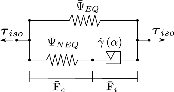
1D representation of the isochoric part of the model
Thermomechanical formulation
A non-isothermal formulation is required to account for the high temperature changes during the curing process. The temperature-dependent Helmholtz free energy function, see [7, 24], is given as
$$\begin{aligned} \varPsi =\varPsi _{EQ}\left( {\mathbf {C}},\theta \right) +{\bar{\varPsi }}_{NEQ}\left( \bar{{\mathbf {C}}}_{e},\theta \right) , \end{aligned}$$
(34)
where \(\bar{{\mathbf {C}}}_{e}\) is the elastic part of the isochoric right Cauchy–Green strain tensor. The deformation gradient in this setting is decomposed into volumetric \({\mathbf {F}}_{vol}\) and isochoric \({\bar{\mathbf {F}}}\) parts,
$$\begin{aligned} {\mathbf {F}}={\bar{\mathbf {F}}}{\mathbf {F}}_{vol}, \end{aligned}$$
(35)
with \({\bar{\mathbf {F}}}=J^{-\frac{1}{3}}{\mathbf {F}}\) and \({\mathbf {F}}_{vol}=J^{\frac{1}{3}}{\mathbf {1}}\), where \(J=\det {\mathbf {F}}\). The isochoric deformation gradient is also split into elastic and inelastic parts as
$$\begin{aligned} {\bar{\mathbf {F}}}={\bar{\mathbf {F}}}_{e}{\bar{\mathbf {F}}}_{i}, \end{aligned}$$
(36)
which enables the definition of the isochoric left and right Cauchy–Green strain tensors, respectively, as follows
$$\begin{aligned} {\bar{\mathbf {b}}}={\bar{\mathbf {F}}}{\bar{\mathbf {F}}}^{T},\quad {\bar{\mathbf {C}}}={\bar{\mathbf {F}}}^{T}{\bar{\mathbf {F}}}. \end{aligned}$$
(37)
The equilibrium part (time-independent) of the free energy is given as
$$\begin{aligned} \varPsi _{EQ}\left( {\mathbf {C}},\theta \right) =t\left( \theta \right) e_{EQ,0}+f_{EQ}\left( \theta \right) \varPsi _{EQ,0}+{\bar{\varOmega }}\left( \theta \right) , \end{aligned}$$
(38)
while the non-equilibrium part takes the form
$$\begin{aligned} {\bar{\varPsi }}_{NEQ}\left( \bar{{\mathbf {C}}}_{e},\theta \right) =t\left( \theta \right) e_{NEQ,0}+f_{NEQ}\left( \theta \right) {\bar{\varPsi }}_{NEQ,0}, \end{aligned}$$
(39)
where \(t\left( \theta \right) =1-\theta /\theta _{0}\) , and the term \({\bar{\varOmega }}\left( \theta \right) \) represents the sum of purely thermal effects on the free energy due to the heat capacity,
$$\begin{aligned} {\bar{\varOmega }}\left( \theta \right) ={\bar{C}}\left( \theta \right) -{\bar{C}}\left( \theta _{0}\right) +\theta \left[ {\bar{\varUpsilon }}\left( \theta _{0}\right) -{\bar{\varUpsilon }}\left( \theta \right) \right] , \end{aligned}$$
(40)
and the functions \({\bar{C}}\left( \theta \right) \) and \({\bar{\varUpsilon }}\left( \theta \right) \) are defined as
$$\begin{aligned} {\bar{C}}\left( \theta \right) =\int _{\theta _{0}}^{\theta }{\bar{c}}_{v}\left( \xi \right) d\xi \quad \text {and}\quad {\bar{\varUpsilon }}\left( \theta \right) =\int _{\theta _{0}}^{\theta }\frac{{\bar{c}}_{v}\left( \xi \right) }{\xi }d\xi , \end{aligned}$$
(41)
with \({\bar{c}}_{v}\) as the heat capacity of a stress free body, which is assumed to have a linear dependency on temperature as follows
$$\begin{aligned} {\bar{c}}_{v}\left( \theta \right) =c_{1}\theta +c_{0}, \end{aligned}$$
(42)
where \(c_{0}\) and \(c_{1}\) are material parameters and \(\theta _{0}\) is the reference temperature. Moreover, the internal energy components are given as
$$\begin{aligned} e_{EQ,0}=\kappa _{0}\alpha _{v}\theta _{0}\ln \left( J\right) ,\quad e_{NEQ,0}=0, \end{aligned}$$
(43)
considering the material bulk modulus \(\kappa _{0}\) and the thermal expansion coefficient \(\alpha _{v}\) at reference temperature \(\theta _{0}\). The temperature dependency of the mechanical part of the free energy reads
$$\begin{aligned} f_{EQ}\left( \theta \right) =f_{NEQ}\left( \theta \right) =\frac{\theta }{\theta _{0}}-\frac{\theta [\tanh \left( b\left( \theta -\theta _{0}\right) \right) ]^{3}}{\theta _{0}+a}, \end{aligned}$$
(44)
which accounts for the glass transition temperature of the rubber, where a and b are material constants. The equilibrium part of the free energy at reference temperature reads
$$\begin{aligned} \varPsi _{EQ,0}=U_{0}\left( J\right) +{\bar{\varPsi }}_{EQ,0}, \end{aligned}$$
(45)
where the volumetric energy \(U_{0}\) is given as
$$\begin{aligned} U_{0}\left( J\right) =\kappa _{0}\left( J-\ln \left( J\right) -1\right) , \end{aligned}$$
(46)
and the isochoric energy \({\bar{\varPsi }}_{EQ,0}\) is defined using the cross-linking part of the extended tube model strain energy function [18],
$$\begin{aligned} {\bar{\varPsi }}_{EQ,0}&={\bar{\varPsi }}_{0}\left( {\bar{\mathbf {b}}}\right) \nonumber \\ \frac{G_{c}}{2}&= \left[ \frac{\left( 1-\delta ^{2}\right) \left( I_{{\bar{b}}}-3\right) }{1-\delta ^{2}\left( I_{{\bar{b}}}-3\right) }+\ln \left( 1-\delta ^{2}\left( I_{{\bar{b}}}-3\right) \right) \right] , \end{aligned}$$
(47)
defined in terms of the first invariant of the isochoric left Cauchy–Green strain tensor \(I_{{\bar{b}}}=\text {tr}\left( {\bar{\mathbf {b}}}\right) =\text {tr}\left( {\bar{\mathbf {C}}}\right) \). The non-equilibrium branch has a similar form
$$\begin{aligned} {\bar{\varPsi }}_{NEQ,0}&={\bar{\varPsi }}_{0}^{v}\left( {\bar{\mathbf {b}}}_{e}\right) \nonumber \\ \frac{G_{c}^{v}}{2}&= \left[ \frac{\left( 1-\delta _{v}^{2}\right) \left( I_{{\bar{b}}_{e}}-3\right) }{1-\delta _{v}^{2}\left( I_{{\bar{b}}_{e}}-3\right) }+\ln \left( 1-\delta _{v}^{2}\left( I_{{\bar{b}}_{e}}-3\right) \right) \right] , \end{aligned}$$
(48)
but it is defined in terms of the elastic isochoric Cauchy–Green strain tensor \(I_{{\bar{b}}_{e}}=\text {tr}\left( {\bar{\mathbf {b}}}_{e}\right) =\text {tr}\left( {\bar{\mathbf {C}}}_{e}\right) \). The material parameters in the previous equations are \(G_{c}\), \(\delta \), \(G_{c}^{v}\) and \(\delta _{v}\). The thermal material parameters required in the previous equations are taken from [1] and are given in Table 1. These parameters will not be changed in the upcoming examples.
Stress response and inelastic evolution law
The material stress response is the sum of volumetric and isochoric Kirchhoff stresses resulting from the free energy functions defined in the previous sections,
$$\begin{aligned} \varvec{\tau }&=f_{EQ}\left( \theta \right) \left( \varvec{\tau }_{vol,0}^{e}+\varvec{\tau }_{iso,0}^{e}\right) \nonumber \\&\quad +\, t\left( \theta \right) \varvec{\tau }_{e,0}+f_{NEQ}\left( \theta \right) \varvec{\tau }_{iso,0}^{v}, \end{aligned}$$
(49)
where
$$\begin{aligned}&\varvec{\tau }_{vol,0}^{e}=JU_{0}^{\prime }\left( J\right) {\mathbf {1}},\quad \varvec{\tau }_{e,0}=Je_{EQ,0}^{\prime }\left( J\right) {\mathbf {1}}, \end{aligned}$$
(50)
$$\begin{aligned}&\varvec{\tau }_{iso,0}^{e}={\mathbb {P}}:\varvec{\tau }_{0}^{e},\quad \varvec{\tau }_{0}^{e}=2\partial _{\varvec{{\bar{b}}}}{\bar{\varPsi }}_{0}^{e}\left( \varvec{{\bar{b}}}\right) \varvec{{\bar{b}}}, \end{aligned}$$
(51)
$$\begin{aligned}&\varvec{\tau }_{iso,0}^{v}={\mathbb {P}}:\varvec{\tau }_{0}^{v},\quad \varvec{\tau }_{0}^{v}=2\partial _{\varvec{{\bar{b}}}_{e}}{\bar{\varPsi }}_{0}^{v}\left( \varvec{{\bar{b}}}_{e}\right) \varvec{{\bar{b}}}_{e}. \end{aligned}$$
(52)
The fourth order deviatoric projection tensor \({\mathbb {P}}_{abcd}=1/2\left[ \delta _{ac}\delta _{bd}+\delta _{ad}\delta _{bc}\right] -1/3\left[ \delta _{ab}\delta _{cd}\right] \) is calculated with the help of the Kronecker delta \(\delta \).
The inelastic response of the material stemming from viscoelasticity and the vulcanization process is defined, similar to the concept of finite viscoplasticity [28], by the flow rule
$$\begin{aligned} {\mathcal {L}}_{v}\left( {\bar{\mathbf {b}}}_{e}\right) ={\dot{\bar{\mathbf {b}}}}_{e}-{\varvec{l}}_{iso}{\bar{\mathbf {b}}}_{e}-{\bar{\mathbf {b}}}_{e}{\varvec{l}}_{iso}^{T}=-2{\dot{\gamma }}{\varvec{N}}_{P}{\bar{\mathbf {b}}}_{e}, \end{aligned}$$
(53)
where \({\mathcal {L}}_{v}\) is the Lie derivative, and \({\varvec{l}}_{iso}={\dot{\bar{\mathbf {F}}}}{\bar{\mathbf {F}}}^{-1}\) is the isochoric velocity gradient. Using this definition, the inelastic deformation rate is prescribed by the direction of the driving stress \({\varvec{N}}_{P}\) and the effective strain rate \({\dot{\gamma }}\). The driving stress is given in terms of the isochoric inelastic Kirchhoff stress as
$$\begin{aligned} {\varvec{N}}_{P}=\frac{\varvec{\tau }_{iso,0}^{v}}{\left\| \varvec{\tau }_{iso,0}^{v}\right\| },\quad \left\| \varvec{\tau }_{iso,0}^{v}\right\| =\sqrt{\varvec{\tau }_{iso,0}^{v}:\varvec{\tau }_{iso,0}^{v}}, \end{aligned}$$
(54)
and the effective strain rate \({\dot{\gamma }}\), in analogy to [11], is defined as
$$\begin{aligned} {\dot{\gamma }}=f_{NEQ}{\dot{\gamma }}_{0}\left( \frac{\tau _{0}^{v}}{{\hat{\tau }}}\right) \left( 1-\alpha \right) ^{p}, \end{aligned}$$
(55)
where \(\tau _{0}^{v}\) is an effective stress measure
$$\begin{aligned} \tau _{0}^{v}=\frac{1}{\sqrt{2}}\sqrt{\varvec{\tau }_{iso}^{v}:\varvec{\tau }_{iso}^{v}}, \end{aligned}$$
(56)
and \({\dot{\gamma }}_{0}/{\hat{\tau }}\) is a material constant.
Finally, the term \(\left( 1-\alpha \right) ^{p}\) in Eq. (55) introduces the effect of rubber vulcanization, where p is a material constant. A value of \(\alpha =0\) keeps the inelastic branch of the rheology fully viscoelastic to represent the uncured state. A value of \(\alpha =1\), on the other hand, deactivates the evolution law to convert the inelastic branch to fully hyperelastic. The evolution of the variable \(\alpha \) is described in the next section.
Degree of vulcanization
It is assumed that the volumetric part of the model is the same for both cured and uncured rubber. The isochoric part, on the other hand, is different, where the uncured rubber exhibits a viscoelastic response, while cured rubber shows hyperelastic behavior. Uncured rubber is modeled with a rate independent part of the isochoric free energy \({\bar{\varPsi }}_{EQ}\), as well as a rate dependent part \({\bar{\varPsi }}_{NEQ}\). However, the vulcanization process causes the rate dependent branch to gradually become elastic by deactivating the viscoelastic evolution law \({\dot{\gamma }}\left( \alpha \right) \). In this way, the final result of vulcanization yields the cured rubber model as the sum of the two parts \({\bar{\varPsi }}_{EQ}\) and \({\bar{\varPsi }}_{NEQ}\).
If the properties of uncured and cured rubber are defined, one can introduce a variable \(\alpha \), which represents the degree of vulcanization depending on temperature \(\theta \) and time t, where \(\alpha \) can have a value of 0 for the fully uncured state and 1 for the fully cured state. In between these limit values, and based on experimental observations, the degree of vulcanization can be described for a constant temperature by the logistic function
$$\begin{aligned} \alpha (t,\theta )=\frac{1}{1+\left( \frac{1}{\alpha _{0}}-1\right) \exp \left( -k\left( \theta \right) \beta \left( \theta \right) t\right) }, \end{aligned}$$
(57)
where \(\alpha _{0}\) is an initial value of vulcanization that is assumed to exist before the curing starts. Furthermore, k is a parameter that controls the speed of vulcanization and can be expressed in terms of temperature as
$$\begin{aligned} k\left( \theta \right) =k_{max}+\frac{k_{max}\left( \zeta -1\right) }{1+\left( \frac{\theta -273.15\text {K}}{k_{1}}\right) ^{k_{2}}},\;\theta \ge 273.15\text {K}, \end{aligned}$$
(58)
where \(k_{max}\) is a material constant that represents the maximum value of \(k\left( \theta \right) \), while the parameter \(\zeta \) gives the initial value of \(k\left( \theta \right) \) at low temperature as \(\zeta k_{max}\). The function \(k\left( \theta \right) \) is also corrected by a polynomial function \(\beta \) as follows
$$\begin{aligned} \beta \left( \theta \right)&=\beta _{0}+\beta _{1}\left( \theta -273.15\,\text {K}\right) \nonumber \\&\quad +\, \beta _{2}\left( \theta -273.15\,\text {K}\right) ^{2}\nonumber \\&\quad +\, \beta _{3}\left( \theta -273.15\,\text {K}\right) ^{3},\;\theta \ge 273.15\,\text {K}. \end{aligned}$$
(59)
The expression in Eq. (57) is a closed form which enables the calculation of the state of cure at a constant temperature. In order to adapt it for variable temperatures during finite element simulations, the rate equation
$$\begin{aligned} {\dot{\alpha }}(\theta )=k\left( \theta \right) \beta \left( \theta \right) \alpha \left( \theta \right) \left( 1-\alpha \left( \theta \right) \right) \end{aligned}$$
(60)
is used. Based on experimental data in [27], Table 2 summarizes the identified material parameters in [1] for the curing law, which will be used in the upcoming examples. The history variables, which need to be remapped in this model, are the degree of vulcanization \(\alpha \) and the inverse of the inelastic isochoric right Cauchy–Green tensor \({\bar{\mathbf {C}}}_{i}^{-1}=\left( {\bar{\mathbf {F}}}_{i}^{T}{\bar{\mathbf {F}}}_{i}\right) ^{-1}\).
Numerical examples
Indentation problem
An indentation problem similar to the one analyzed in [30] is studied to clarify the behavior of the ALE formulation. The specimen is considered in plane strain conditions and the geometry can be seen in Fig. 5, where the boundary conditions for the spatial and the material displacements are also shown. The rubber material used is defined by the constants \(G_{c}=0.2\;\text {MPa}\), \(\delta =0.1\), \(G_{c}^{v}=2\;\text {MPa}\), \(\delta _{v}=0.25\), \({\dot{\gamma }}_{0}/{\hat{\tau }}=0.02\;\text {s}^{-1}\,\text {MPa}^{-1}\), and \(p=1\). Displacements of 50 mm are applied at the top and the reaction force is measured. The concentration of stresses at the tip of the loading area leads to large element distortion in the Lagrangian simulation, see Fig. 6. The ALE simulation is performed with smoothing steps carried out at regular intervals every five Lagrangian steps, where the total number of 100 time increments is used and the total simulation time is 60 s. Different values of the smoothing parameters \(\mu _{{\mathcal {X}}}/\mu _{\psi }\) are used as can be seen in Figs. 6 and 7. A superior spatial mesh smoothing is achieved by smaller values of \(\mu _{{\mathcal {X}}}/\mu _{\psi }\), where the rearrangement of the spatial mesh is accompanied by the movement in the material mesh. Furthermore, Fig. 7 shows the stiff response of the Lagrangian method at higher displacements, whereas the ALE approach preserves a softer material response.
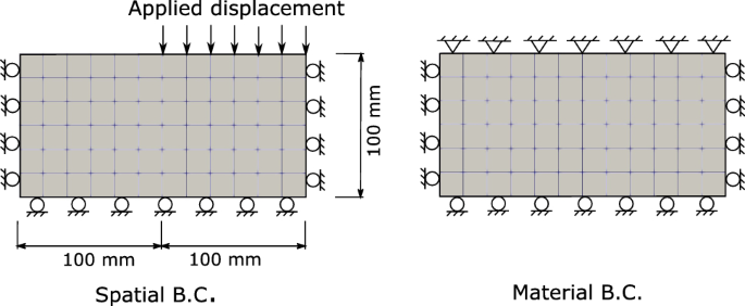
Indentation problem, geometry and boundary conditions
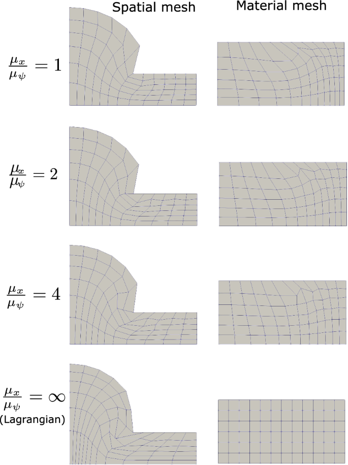
Indentation problem, material and spatial meshes for different values of \(\mu _{{\mathcal {X}}}/\mu _{\psi }\)
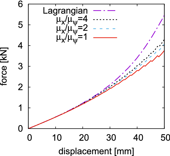
Indentation problem, force displacement response for different values of \(\mu _{{\mathcal {X}}}/\mu _{\psi }\)
Rubber molding problem
Molding of a green rubber sample [19] is studied in this example to compare the performance of the ALE formulation to the Lagrangian solution. The geometry of the problem is shown in Fig. 8, where the mold is simulated with fixed degrees of freedom, and contact between rubber and mold is solved with a node to surface algorithm using the penalty method with a contact penalty parameter of 100 MPa. A total displacement of u = 12 mm is prescribed at the top surface of the rubber specimen with a loading rate of 0.5 mm/s. The material constants for the rubber are taken as \(G_{c}=0.2\,\text {MPa}\), \(\delta =0.1\), \(G_{c}^{v}=4\,\text {MPa}\), \(\delta _{v}=0.1\), \({\dot{\gamma }}_{0}/{\hat{\tau }}=0.08\;\text {s}^{-1}\,\text {MPa}^{-1}\), and \(p=1\). For the ALE simulation, a smoothing parameter of \(\mu _{{\mathcal {X}}}/\mu _{\psi }=2\) is used and smoothing steps are carried out at regular intervals every four Lagrangian steps. The number of time increments used is 800 steps for both ALE and Lagrangian simulations. It can clearly be observed in Figs. 9 and 10 that the Lagrangian approach is inapplicable of solving the problem up to full displacement. Large element distortions leads to the termination of the solution at u = 9.9 mm. On the other hand, the ALE approach keeps the mesh with minimal distortion and enables the continuation of the simulation. Figure 11 shows the evolution of the material and spatial mesh at different loading stages.
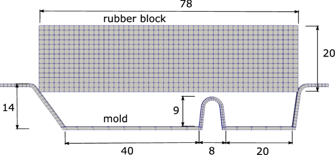
Rubber molding problem, geometry and FE discretization, dimensions in (mm)
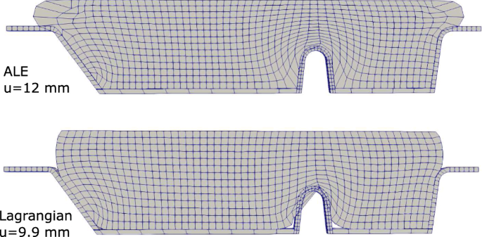
Rubber molding, deformed meshes obtained by ALE and Lagrangian simulations
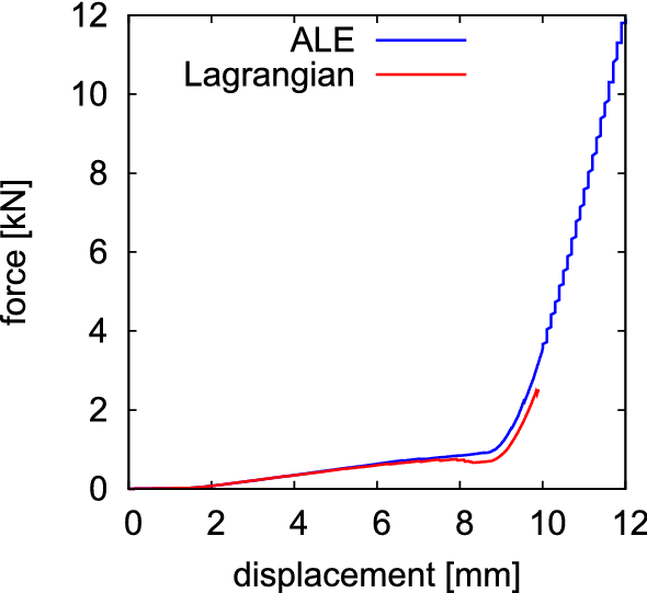
Rubber molding, force displacement response obtained by ALE and Lagrangian simulations
Forming and curing of a tire cross-section
The simulation of the forming and curing process of a tire cross-section is addressed in this example. This involves the molding of the tire under inflation pressure and the application of heat for an appropriate period of time until vulcanization of the rubber is complete and the tire has achieved its final desired shape. The geometry of the tire cross-section, its layers and the mold are shown in Fig. 12. For the purpose of this work, the rubber layers (tread, inner liner, sidewall, bead filler) are all modeled using the rubber curing material model explained in the previous section, with the material constants \(G_{c}=0.2\,\text {MPa}\), \(\delta =0.1\), \(G_{c}^{v}=4\,\text {MPa}\), \(\delta _{v}=0.1\), \({\dot{\gamma }}_{0}/{\hat{\tau }}=0.2\;\text {s}^{-1}\,\text {MPa}^{-1}\), and \(p=1\). The carcass and the belt layers are simulated using solid elements and Neo-Hookean material with increased stiffness. The material parameters for the carcass are \(\kappa =100\,\text {MPa}\), \(G=50\,\text {MPa}\), and the parameters for the belt are \(\kappa =100\,\text {MPa}\), \(G=200\,\text {MPa}\). Likewise, the bead is simulated using Neo-Hookean material with \(\kappa =8\times 10^{5}\,\text {MPa}\), \(G=6\times 10^{5}\,\text {MPa}\). The bead vertical movement is fixed and plane strain conditions are applied to the cross-section.
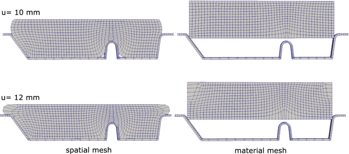
Rubber molding, evolution of the spatial and material meshes
ALE remeshing is activated only around the grooves where high distortion is expected, in the domain specified in Fig. 12. The ALE and the Lagrangian elements are connected through shared nodes on the boundary of the ALE domain. ALE smoothing steps are performed every four Lagrangian steps with a smoothing parameter of \(\mu _{{\mathcal {X}}}/\mu _{\psi }=3.5\). Smoothing steps continue until time = 260 s, where the tire is fully formed and no further re-meshing is needed. Regarding the contact, the mold degrees of freedom are fully restrained and node to surface contact between tire and mold is defined, where the mold surface is taken as master. Moreover, a standard contact penalty method is used with a contact penalty parameter of 500 MPa.
Pressure loading of 0.25 MPa is applied to the inner surface of the tire according to the loading pattern shown in Fig. 13. Furthermore, the inner and the outer surfaces of the tire are heated by temperature increase of \(\varDelta \theta =130\) K, also according to the loading pattern shown in Fig. 13. The results are given in Fig. 14, where the heating of the molded tire leads to the evolution of the degree of vulcanization. This is an irreversible process, where the new cured tire has its new shape and new properties and does not spring back to the initial state after cooling and removal of the pressure.
The advantage of the ALE approach can clearly be seen in this example, as the Lagrangian simulation of the same problem causes extreme distortion of the mesh and cannot resolve the shape of the grooves as can be seen in Fig. 15. This example also shows the possibility of combining ALE finite elements with Lagrangian finite elements in the same simulation.
An increase of about 5-15% in computational time depending on the problem is observed in case of ALE simulations when compared to the corresponding Lagrangian solution. Smoothing and remapping steps are performed after several pure Lagrangian steps, which contribute to the reduction of the solution time. It is also observed that the main contribution to the increase in computing time comes from the smoothing, rather than the remapping step. The two Newton iterations and the element search algorithm are only executed if required, which is limited to elements where large material mesh displacements occur. Moreover, the Newton iterations performed during history remapping are just solving three-component equations, while the element search algorithm checks closer elements first, and, thus, does not need to loop over the entire list of elements.
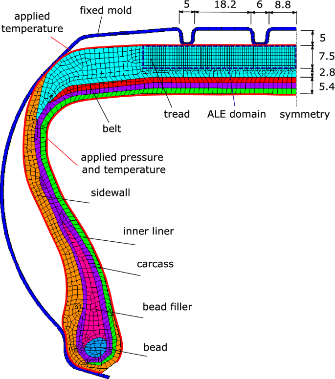
Tire cross-section, details of the tire layers and FE discretization, dimensions in (mm)
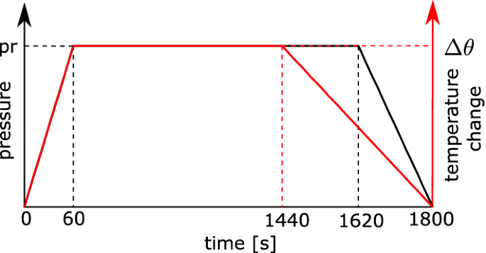
Loading pattern for the applied pressure and temperature on the tire cross-section
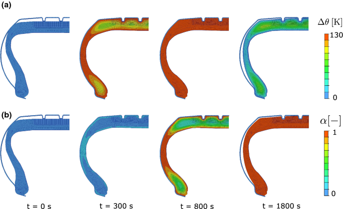
Tire cross-section, evolution of a the temperature field and b the degree of vulcanization
Conclusions
A robust Arbitrary Lagrangian–Eulerian framework for thermomechanical simulations of viscoplastic problems with special focus on rubber curing and tire manufacturing has been implemented. An advanced phase transition rubber curing model, which predicts the thermomechanical vulcanization process, is incorporated into the staggered ALE finite element method. To date, ALE formulations have mostly been applied to basic finite strain plasticity models for the simulation of metals. In most of these cases, Lagrangian simulations are still largely acceptable, see the examples in [2, 26]. In contrast, the ALE formulation for soft rubber material seems critical for successful molding simulations as it has been demonstrated by the examples in this paper. The examples presented show the advantage of the ALE formulation in reducing mesh distortion and allowing full molding of rubber material during tire manufacturing. The capability of the constitutive model to represent the vulcanization and the transformation of rubber from green to cured state is also demonstrated in the last example.
The ALE approach based on tracking both, the material and the spatial configurations, as proposed in [2, 30] has been used, which proved to provide a more suitable way to incorporate rubber hyperelasticity and multiplicative finite strain inelasticity, with no projection required for the elastic variables. Furthermore, operator split of the ALE solution into smoothing, remapping and Lagrangian steps leads to a very efficient simulation with minimal increase in computational time, as well as it allows the straightforward incorporation of already available Lagrangian finite elements. The smoothing step is based on solving a fictitious hyperelasticity problem to optimize both material and spatial meshes. This avoids the need of geometric rezoning procedures, which become complex in 3D applications. Another advantage of tracking the material mesh is that it can be used to remap the history variables by an implicit particle tracking scheme. Unlike the explicit Lax–Wendroff and Godunov schemes, the particle tracking does not depend on the number of history variables or require the evaluation of spatial gradients of these variables.
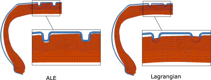
Tire cross-section, comparison of the final results obtained by the ALE and Lagrangian approach
The main focus of this paper was to investigate if the ALE approach has an advantage over pure Lagrangian simulations. However, the validation of the approach for real tire molding experiments requires specific experimental data with complex geometries and multiple materials characterization, which will be the subject of future work.
Source: https://link.springer.com/article/10.1007/s00466-021-02005-5